Category Archives: Arcade

Arcade Cabinet – Part 2

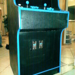
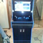
The arcade cabinet is complete! Construction was finished a couple months ago but I never got around to writing an update. See below for an outline of what was left after the first post.

Painting, T-Molding, and Plexiglass

I decided to go with a blue/black theme for the color scheme. The cabinet itself was sanded and then painted with two coats of semi-gloss black paint.

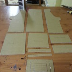
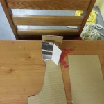
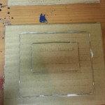
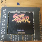
The screen bezel plexiglass was cut to size, masked and then backpainted using gloss black Tremclad spray paint for an even finish. The control panel plexiglass was cut to size, and using the template I drew I marked off the locations of the button holes and joystick holes. The control panel plexiglass was then backpainted in the same manner as the screen bezel. The marquee plexiglass was cut to size, but not backpainted so I could insert a graphic behind it.

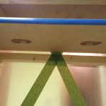
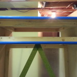
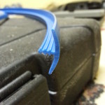
I went with blue T-molding to finish the edges of the cabinet. Using a router, a slot was drilled along all edges of the cabinet. The T-molding was lined up in the slot and gently tapped in using a rubber mallet. I was considering using wood glue to keep the T-molding in place, however the slot itself was pretty tight so a pressure-fit was more than enough.

 Monitor Installation and Wiring

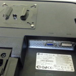
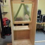
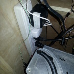
I had originally ordered a VESA mounting bracket for the monitor in the cabinet – however due to space constraints the design had to be altered to remove the piece of wood that would act as the backing bracket for the screen. Because of this I had to pressure-fit the monitor in place, and secure it from falling out by building a twine ‘harness’. You can see what I mean in the following pictures.

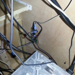
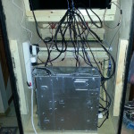
The cabinet interior is surprisingly small! Again because of this the wiring turned into a bit of a rats’ nest. I decided to use the same twine ‘harness’ to lift all of the cables off of the floor of the cabinet. This was to prevent interference with the coin mechanisms and coin collection bucket.

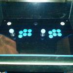
First task was to install the buttons and joysticks. This was fairly simple to do as the buttons are just pressure-fit into the control panel. The joysticks were rear-mounted to the control panel with 1/2″ screws. Each of the buttons and both joysticks were then  wired up to the USB controller board.

The computer was mounted to the bottom of the cabinet floor and secured in place with screws through the bottom of the chassis. I had to drill a hole through the aluminum case to access the power supply for the coin mechanisms.

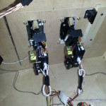
The coin mechanisms were installed in the front access door, and wired up to the computer’s ATX power supply +12V line, the 12V relay, and the USB controller boards.

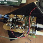
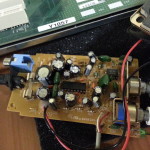
The amplifier board was mounted to the interior side of the cabinet, wires were ran to both speakers in the top, and power connected to the board. It was mounted face down for easy access if I want to turn the volume up or down.

The marquee light was installed in the top of the cabinet. I went with a LED strip light ran around the interior edges of the marquee space. I added a reflector to the back of the marquee to give even lighting to the marquee graphic.

The power button was installed below the marquee space, and a wire ran down the cabinet interior to the PC motherboard. This allows me to turn on the cabinet from the outside, as well as turn on all the components at once using the smart power strip I installed inside.

Power On!

After wiring everything up, it’s time to power it on! I had setup the operating system, MAME emulator and frontend software a couple months in advance so everything would be ready to go.

Here are the details:

  • Windows XP SP3
    • Disabled explorer shell, boots directly to frontend
    • Disabled XP theme for performance
    • Disabled network adapters
    • Custom boot screen when the cabinet is starting
  • GroovyMAME V0.151 (Multiple Arcade Machine Emulator)
    • This is what actually emulates the arcade games, allowing them to be played on a PC
    • Anti-nagscreen support
    • Hi-score support
  • MaLa Frontend V1.74
    • Provides a simple UI for selecting games

Conclusion

This has been an amazing project to work on. Two years in the making and it’s finally complete! In the past few months since its’ completion, I’ve had dozens of people play it and they’ve all had a blast. It’s been a really great addition to the living room!
Arcade Cabinet – Part 1

Growing up in the 90’s I experienced the shift from traditional arcade gaming to home consoles. While I’ve owned and played a variety of consoles over the past couple decades, nothing quite compares to the noise and intensity of the arcade. I have many fond memories of waiting around at the theater for a movie to start, feeding token after token into House of the Dead or Time Crisis. Even to this day whenever a buddy of mine comes to town we make sure to beat Time Crisis 4 at least once during his stay.

Over the past couple of years I’ve been thinking about building my own custom cabinet at home. It’s been a thought in the back of my mind for a while now, and finally I’ve decided to go ahead and build it. This first post outlines the work and progress I’ve achieved so far.

The Mockup

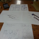
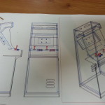
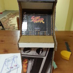
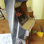
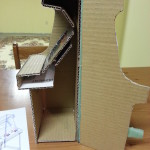
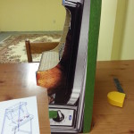
The first thing I did was look around for existing plans. I came across a few online but they were usually huge and suited for the old tube-style monitors. One of the plans I found however was a ‘slim’ cabinet design (which I liked) and so I set about creating a scale model.

The Computer and Monitor

I was thinking of either making a dedicated cabinet (one game board). Early on I was looking into JAMMA harnesses and boards, then I took a look into creating a 4-slot Neo-Geo setup. After looking around for parts and pricing out items, it seemed to be more worth my while to go for an emulated setup. This would mean using MAME + a frontend on an actual PC.

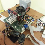
I happened to have an old Dell lying around my place, so I ripped that apart and stripped it down to just the motherboard and other internal components. I’ve put Windows XP on it (fastest to boot on the hardware) and heavily customized it for speed. It also boots straight into the MaLa frontend for choosing the game you would like to play.

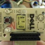
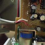
This Dell PC had a strange setup for its power button. It uses a separate board mounted just under the plastic, with a momentary switch soldered onto it. I’ll have to de-solder and re-solder some wires in its place so I can put the power button elsewhere on the cabinet.

Recently I bought a nice 23″ touchscreen monitor to replace my older 21″ office monitor. I’m re-purposing the old one to be the monitor I mount in the arcade cabinet. While this isn’t a real arcade CRT, it will drastically reduce the weight of the cabinet (and the dimensions).

The Speakers

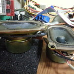
I also had a pair of old PC speakers lying around the house. I’ve re-purposed those to be the speakers in the arcade cabinet.

I disassembled the enclosures and removed the amplifier board. I’m planning on mounting the board on the inside of the cabinet behind the front access door. This way I can still change the volume.

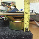
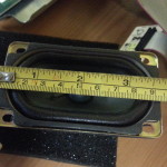
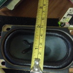
The speaker cones themselves will have to be de-soldered and speaker wire extensions added to them, as they will be mounted way up top in the marquee. I had to do some careful measurements of the cones to make sure they would fit correctly in the marquee area.

Buttons and Joysticks

I researched a variety of buttons and joysticks used in authentic arcade machines. There are two main varieties we are familiar with here in North America – the most popular being Happ (concave face buttons) and Sanwa (convex face buttons on Japanese import games).

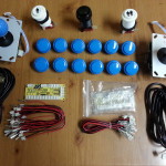
I found a good package deal on Ebay for 10 Sanwa buttons (8 regular sized, 2 smaller) one ball-top joystick, joystick encoder board, wiring harness, and USB cable. I ordered two of these packages – one for each player on my cabinet.

One thing to note – these aren’t legitimate buttons. They are marked as “Sanwa-style buttons” and look slightly different from the real ones. However they seem to be decent enough quality, and will definitely work for my purposes!
Pictured below is the configuration I’ll be using on my control panel. I think 8 buttons per player is excessive, so I’ve gone with 6 per player plus a start button for each and a menu button in the middle.

Coin Acceptors vs Coin Buttons

I originally planned on adding a P1 COIN and a P2 COIN button to my control panel. This would allow each player to insert coins virtually to play the game. However I soon became extremely opposed to this idea after seeing how easy and pointless the games became when the player simply mashed the coin button.

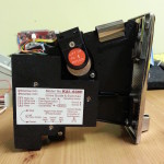
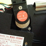
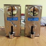
Because of this I decided to go with a more “authentic” game experience and did some research into coin acceptors. Again, the ones I ended up going with were on Ebay. They’re pretty neat – they take a template coin and match any inserted coins against the diameter, thickness, color, and reflectivity of the template. If the coin matches then it’s allowed through and an electrical pulse is triggered – if not then it is rejected out the front coin return.

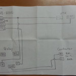
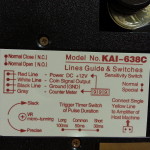
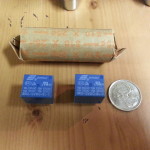
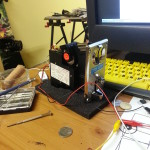
Major issue with the coin acceptors – they are meant for actual arcade cabinets and therefore run on 12V. However, my joystick encoder board is USB and runs on 5V. If i hooked it up directly I would risk frying the port on my motherboard. To get around this I ended up using a relay to cause an “artificial button press” on the controller board when the 12V pulse is sent from the coin acceptor. After an entire evening of fiddling with wires and my multimeter (the English translation of the Chinese instructions were absolutely horrible), I ended up reverse engineering how the circuit worked and created my own “switch” using the relay.

I can’t honestly expect my friends to pay to use my arcade cabinet, so what I’ve done is obtain $10 in quarters to use as tokens in the machine. If we run out of tokens (insert them all) then its a simple matter of opening the access door and retrieving the bucket of coins when necessary.

The Cabinet

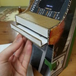
After I built the cardboard mockup I quickly found out that the cabinet was way too short for my height. Because of this I needed to modify the design.

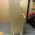
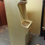
Well… one modification turned into dozens and soon my Dad and I had totally redesigned the cabinet. The total height is just over 6 feet now, with a 36″ height from floor to control panel face. It is 24″ wide and the main body is around 24″ deep.

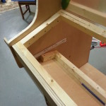
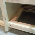
For materials, I opted to use 3/4″ sanded birch plywood. The reason I didn’t go with something more common like MDF was due to the sheer weight of the stuff. It’s HEAVY. The interior framing is done using 2×2’s, and the entire cabinet will be resting on four 3″ rubber wheel casters for ease of movement.

I bought a sheet of plexiglass and cut it up into three pieces – one large piece for the monitor bezel, another for the marquee, and the last as a control panel cover to help protect the paint underneath.

Blue t-molding will trim the edges of the cabinet and match the colors of the buttons and joysticks. We’ve also routed out a slot in the monitor bezel frame which fits the monitor. This brings the monitor closer to the bezel so it doesn’t look “sunken” into the cabinet.

I will be painting the cabinet with semi-gloss black latex paint. Two coats should do the trick due to the fine sanded finish on the birch plywood.

Stay Tuned…

That’s about it for now. Over the next couple weeks I’ll be laying out the control panel buttons, figuring out where to mount the coin acceptors on the front access panel, and deciding where (and especially HOW) to mount all the computer hardware inside the cabinet.